Roll forming is a continuous bending operation in which sheet or strip metal is gradually formed in tandem sets of rollers until the desired cross-sectional configuration is obtained. Roll forming is ideal for producing parts with long lengths or in large quantities.
PROFIL is the roll form design software for every manufacturer of cold roll-formed profiles or seamed tubes from sheet metal and for designers of roll formers and tube mills.
PROFIL enables quicker working and cost reductions in planning, design, calculation and drawing of the profile, the flower pattern (bending steps) and the roll tooling. More..
Working with PROFIL is like working with a CAD system: The drawing of the profile, the flower pattern or the roll tools is permanently displayed on the screen. More..
 New:
New:
Rel 6.3 is available!
New features: New material model and new calculation methods, new material database, new evaluation of strain at band edges - and more. More..
 Neu:
Neu:
New material model
The material model of the PROFIL FEA extension is available now in the PROFIL basic version. These calculation methods have been modified and are based on data from the new material model: Stress of band edge, PSA, spring back, stress on the outside of the bending zone. More..
 New:
New:
New material database
PROFIL contains a new material database with properties and stress-strain curves of leading material suppliers. These data come from tensile tests from the suppliers. Thus the user gets more precise results from the FEA simulation. More..
 New:
New:
Scaling on high resolution monitors
If the user sets a WINDOWS scaling >100% on a high resolution monitor in order to have the font better legible, the content of the PROFIL windows sometimes have been incomplete in the past. The problem now is solved; any scaling and any WINDOWS screen format can be set. Furthermore the screen font has been set to Tahoma that improves the legibility of small fonts. More..
 New:
New:
FEA evaluation
After running the solver the strain at the band edges is shown. More..
 Spanish Version
Novedades para todos los diseñadores de perfilado hispanoparlantes: La nueva versión 6.2 64bit del software de diseño de perfilado UBECO PROFIL está ya disponible en español. Tanto la interfaz de usuario con todas las funciones de menú como los cuadros de diálogo están en español. También el fichero de ayuda de PROFIL y el Manual de Usuario de PROFIL están traducidos al español. More..
 FEA: Automatic Refining
Since the profile is more deformed in the bend zones and at the band edges, it makes sense to double the count of elements in these critical zones. More..
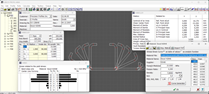
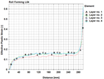
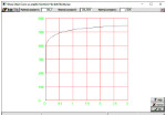
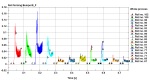 Evaluating the FEA simulation result
After finishing the FEA simulation of the profile project the results are evaluated by using LS-PrePost (included in the LS-DYNA package). In order to relieve the user from time-consuming operations, a Python script has been developed that shows important results as a graphic automatically. The picture shows the forces of the top shafts of each machine stand. The forces are important for configuring the shaft diameter, bearings, cardan shafts, gear box, and the drive power. The script easily can be adapted to individual user's needs. More..
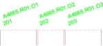 Rotating numbers
If the roll and part numbers are long and the rolls are small, the numbers obscure each other. Now long numbers are rotated automatically in order to prevent obscuring. The angle can be preset. More..
 ActiveX interface to ZWCAD from ZWSOFT
ZWCAD is a low-cost CAD system with perpetual license that is popular in Asia. It is fully DWG compatible and has functions and commands like AutoCAD. Now PROFIL also ist able to transfer drawings and solid models to ZWCAD, just like to AutoCAD, SolidWorks, SolidEdge and BricsCAD via the comfortable ActiveX interface without file transfer. Users of any other CAD system are able to exchange drawings and 3D models via the file formats DXF and STEP. More..
 Fillet
Any two line or arc elements are selected that should be rounded out with each other. Elements between the selected ones are removed, especially correction elements that arose by non-tangential connections in a faulty CAD drawing. More..
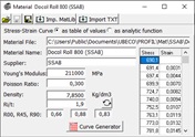
 Stress-Strain-Curve as analytic function
If the designer quickly wants to validate his project by FEA and the exact material data are not available (e.g. from a tensile test), it makes sense to use an approximation. PROFIL's integrated curve generator creates a stress-strain curve by specification of the yield stress, tensile stress, and the curve form. A new feature is to use an analytic function, e.g Swift power law, Voce law with form, Hockett-Sherby law or Stoughton-Yoon hardening law. More..
 Rel 6.0 64bit is available now!
New features: 64bit version for WINDOWS 7,8,10,11 enables efficient handling especially for larger projects during output, optimized FEA simulation speed, new database format SQL 64bit - and much more. More..
 Training Videos are available!
The training lessons show how to define simple and complicated profiles and how to design the flower pattern and the roll tools by deriving the contours from the passes. For this purpose the parameters of the roll forming machine must be determined, this is demonstrated in another video. Now follows the important step to verify by using the finite element analysis, if the designed roll tools actually are able to produce the desired profile cross section within the required allowances. This is shown in a specific video. The result of the design has to be passed to a CAD/CAM system or a CNC lathe; this illustrates another video. Round welded tubes and shaped calibrated tubes (these are welded tubes with any cross-section) are a specific matter covered in a separate video. More..
 3D SolidEdge
3D models can be created in SolidEdge via the comfortable ActiveX interface, either a roll forming stand with or without a profile section or all stands. More..
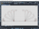
 Automatic Tube Forming
This function creates the flower pattern for a given round tube automatically. The flower consists of the round tube (welding pass) given by the user with any diameter and sheet thickness, a preselected count of fin passes, and the break-down passes. The count is preset in the machine data window. If the round tube should be formed to a shaped tube (i.e. a tube with any cross-section), the calibration passes can be created automatically by using the function Shaped Tubes Calibration. More..
A very new feature is the stress calculation within the whole profile cross section. Thus too high strain also can be recognized if the maximum is not at the band edge, e.g. in case of bending upwards folded edges (hems). More..
 Built-in Slides of the PROFIL FEA Training
While parameterizing the simulation model for the FEA system LS-DYNA, the corresponding slides of the FEA training can be displayed by pressing the help button. So the designer easily remembers the meaning of the input fields without consulting the manual each time. If the info is not sufficient, a further keypress opens the appropriate manual page. More..
 Meshing Preview
When presetting the meshing parameter it is not necessary anymore to try, export the files, and check the meshing. A preview window shows the meshed sheet and the meshed rolls. So the user can see the effect of parameter changes to the FEA model directly during input. More..
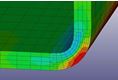
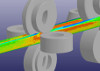
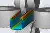
 Comparison Plan vs. Actual Analysis
The passes of the designed flower pattern (light green in the front) are shown in the FEA result if desired. Because contact conditions are not defined, the designed passes have no influence on the simulation result. So the desired cross-section can be compared with the actual formed by the rolls. Unwanted deviation can be detected easily. After modifying faulty rolls the simulation is restarted at the certain stand. More..
 Automatic profile meshing
The sheet meshing must be small at the position of later narrow bend zones. However, the FEA simulation works most robust if the deviation of neighbor elements is not too large. The built-in automatic profile and roll meshing considers this by creating smooth changes. More..
 Short calculation time with shells and solids
The FEA (Finite Element Analysis) simulation of the roll forming process needs amazing short calculation time if the proper simulation model (shell or solid) is selected, the proper CPU count is available, and the FEA system is parameterized optimally. The roll forming experts of UBECO succeeded in close collaboration with the FEA specialists of DYNAmore to optimize the system in order to get short calculation time and stable operation. More..
 Chamfers for threading:
For the FEA simulation, the sheet lead end must be threaded correctly into the roller stands. In addition to the guiding function a new feature is available: The sheet lead edges can be chamfered in width and in thickness direction. More..
 Separate calculation method
For special purposes e.g. stiffening corrugations or other applications, when deep drawing effects occur, a separate calculation method of the developed length can be assigned to each profile arc element. The user can select between a standard method, such as Oehler, DIN, centerline, or define user methods that can be equipped with empirical corrections. The new dialog window gives an overview of the existing calculation methods, enables defining user methods, and applying the methods to the profile's arc elements. In this window, the position of the neutral line is shown as a graph dependent on ri/s (ratio inner radius/sheet thickness). More..
The goal of the software development has been: The new PROFIL user should continue using his preferred CAD system. For this reason PROFIL was designed to work closely with any CAD system. A new feature is the comfortable ActiveX interface to SolidEdge and BricsCAD. More..
In order to meet varying demands, the FEA system LS-DYNA allows selecting between shell and solid elements. Shell elements are well suited for pure bending; the calculation is quick and effective. However, limits exist if massive forming occurs. In this case solid elements are more advantageous, the calculation, however, needs more time. The designer can select between shell and solid elements dependent on his application. The software creates the simulation model for the FEA system LS-DYNA automatically. In case of solid model, selection among 2, 4, 6, or more elements in sheet thickness direction is possible. More..
It's a common practice to keep the strip under tension by gradually increasing the roll pitch diameters. It prevents vertical buckling and reduces the spring back between the stands. After choosing the increment PROFIL inserts the appropriate working diameters in all stands. More..
 FEA simulation of the roll forming process with LS-DYNA
After designing roll forming tools for a new profile the designer wants to verify if the roll tools are able to produce the profile cross-section within the given allowances. The FEA (Finite-Element-Analysis) simulation of the roll forming process enables the designer to validate and optimize his roll form design at an early stage. New is the interface to the FEA system LS-DYNA. After designing the roll tools the files with the FEA model are created by key-press. In case the sheet is pre-punched, bore holes and cut-outs can be defined in a CAD drawing easily. After roll tool modification, the FEA simulation can be restarted at any roll forming stand. More..
 Expanded Undo /Redo functions:
The function name of the next step is shown and the count of steps can be preset by the user. Henceforward, the user does not need to guess anymore, which function will be reversed next; the software shows it beforehand. More..
 New Functions For Flexible Design
Varying profile width, varying strip width, varying sheet thickness in the same roll forming machine, is this possible? It's a hard work to design the roll tools in such a flexible way that they are able to consider varying product properties without or with little set-up time and effort only. The developers of the roll form design software had some good ideas how to make the designer's work easier and clearer. New functions just like modifying strip width, modifying sheet thickness, and a new kind of replaceable spacers make it possible to design the roll tools flexibly for varying product properties. More..
The new kind of spacer rolls are handled as forming roll objects. They can be selected by mouse-click, can be dimensioned and modified, and they are named dependent on special number keys. If needed, spacer rolls are split into shims automatically. More..
 Multi Axles Machine
The automotive industry and also other applications require more and more complex roll formed profiles. In order to form such profiles on a roll forming machine, it often is necessary to have additional side axles with inclined angles that plunge into the open cross-section. This makes it more easy to form the inner radii precisely, that are not accessible for horizontal top rolls. For this purpose additional side axles with arbitrary inclination angle can be created in the machine window. More..
are handled in the profile project completely, and are saved into the project file. The machine file in its previous form now is used for machine data exchange between different projects. In the machine window, machine design is fully interactive. More..
 Shaped Tubes
are tubes with any cross-section that are formed from a welded tube by using calibrating stands (Turk's Heads). In this process the initial shape should come as close as possible to the final shape. If the shaped tube has nearly a square form (with same width and height), it should be formed from a welded round tube. If the shaped tube is either quite large and flat or quite high and narrow, an ellipse is the appropriate initial shape. Also calibrating by keeping the cross-section unchanged is often used. More..
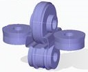
 3D Models in CAD
creates the 3D model of the current stand or of all stands of the whole roll forming line or tube forming line. The model is transferred to AutoCAD or SolidWorks via the ActiveX interface. More..
 3D Models in STEP Format
CAD neutrality has always been an important goal for the development of the PROFIL concept. The user should have no restrictions in choosing the right CAD system, but he should use the CAD system of his own needs in combination with PROFIL. This goal is now achieved also in the 3D field by the new STEP interface. The 3D model of the profile pass and the roll tools can be exported in a STEP file in accordance with DIN ISO 10303. More..
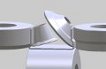
 Folding the band edge
When a folded band edge with inner radius zero is formed to a hem, the material´s spring back causes a considerable problem. The sheet surfaces should touch closely and should not spring up. More..
 Trapezoidal Profile Forming
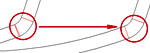
When wide sheet metal strips are roll formed to a trapezoidal profile, the course of the band edge has a crucial influence on the quality of the product. On the one hand the course must be as short as possible in order to form the band edge elastically only. The shortest connection between two points is the straight line - but the band edge is creased both at the machine entrance and exit. This is why the second important point of view for choosing the right band edge course is the tangential connection at entrance and exit. In practice, a linear function with fillet radii is often used or a cosine function. More..
 Automatic Flower Creation
speeds up the design for recurring types of profiles substantially. The know-how is taken from a knowledge base that increases more and more as the system is used. Thus PROFIL has become an expert system. More..
 Automatic Creation Of Assembly Plan
After designing the roll tools for a new roll formed profile the production drawings still have to be created. A Roll Assembly Plan for each roll formed stand is necessary that shows the mounted rolls and the separated rolls with dimensioning in addition. A prepared Drawing Template from a DXF file is opened and the stand drawing is created in the center automatically. Then the rolls just can be picked up by mouse-click and copied or moved to another position. More..
While dealing with an inquiry the designer needs calculation data from similar profiles that are produced in the past. Designing new roll tools should consider experience from earlier projects. The profile catalogue gives a quick overview of all produced roll formed parts. More..
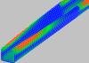 Profile Stress Analysis (PSA)
is the second step of the three step quality management concept. The sheet metal strip is divided into small shell elements and the geometrical deformation while passing through the roll forming machine is calculated. From it the strain and stress in the whole profile is obtained and displayed by colors. Important e.g. if edges are folded and the folds are bent, this means when the maximal stress is not at the band edge. More..
Profile Stress Analysis (PSA)
is the second step of the three step quality management concept. The sheet metal strip is divided into small shell elements and the geometrical deformation while passing through the roll forming machine is calculated. From it the strain and stress in the whole profile is obtained and displayed by colors. Important e.g. if edges are folded and the folds are bent, this means when the maximal stress is not at the band edge. More..
The designer of cold roll-formed profiles wants to re-use rolls from older projects for saving money. To find suited rolls for his new project by using search filters, he needs the roll stock management. More..
 Virtual Roll Forming Machine (VRM)
is the third step of the quality management concept. The FEA simulation of the roll forming process enables the designer to validate and optimize his roll form design at an early stage before the rolls are manufactured to ensure that the final product meets the particular needs. To proceed this very precise calculation of the stress and the longitudinal deformation within the whole profile, an interface has been provided to the leading FEA systems LS-DYNA. More..
Virtual Roll Forming Machine (VRM)
is the third step of the quality management concept. The FEA simulation of the roll forming process enables the designer to validate and optimize his roll form design at an early stage before the rolls are manufactured to ensure that the final product meets the particular needs. To proceed this very precise calculation of the stress and the longitudinal deformation within the whole profile, an interface has been provided to the leading FEA systems LS-DYNA. More..