|
|
Virtual Roll Forming Machine (VRM)
is the third step of the three steps quality management concept. After designing roll forming tools for a new profile the designer wants to verify if the roll tools are able to produce the profile cross-section within the given allowances. The FEA (Finite-Element-Analysis) simulation of the roll forming process enables the designer to validate and optimize his roll form design. To enable the designer to benefit from the FEA result without being an FEA expert, the software PROFIL has a built-in interface to the leading FEA system LS-DYNA from Livermore Software Corp. USA.
Compared with step 1 (stress of band edge) and step 2 (PSA - Profile Stress Analysis) the FEA simulation has the advantage that it calculates most precisely not only stress and strain. FEA is also able to predict the profile shape that is formed by the designed rolls and shows unwanted deformations. Since more computing time is required, it makes sense to use the FEA simulation at the end of the design process. More: Quality Management in Rollform Design
|
|
|
Proceeding the simulation:
After designing the flower pattern and the roll tools the parameters for the simulation like meshing longitudinal and transversal, material etc. are entered. Then PROFIL creates the files with the simulation model automatically. Afterwards the LS-DYNA solver can be started and after performing the FEA simulation the designer gets precise information about the stress and strain within the whole profile and the deformation. By dimensioning the CAD drawing the designer can check, if the final profile is within the given allowances. If not, he can modify his design before the roll tools are manufactured.
|
|
|
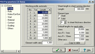
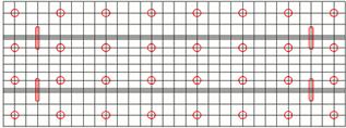
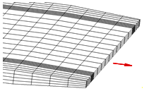
Automatic profile and roll meshing:
The sheet meshing must be small at the position of later narrow bend zones and can be wider in the straight parts or zones of less bend. However, the finite element simulation works most robust if the length deviation of neighboring elements is not too large. The built-in automatic profile and roll meshing considers this by creating smooth changes.
|
|
|
Automatic refining:
Since the profile is more deformed in the bend zones and at the band edges, it makes sense to double the count of elements in these critical zones. Thus a smaller count can be preset as basic setting. This lowers the simulation time, especially if large line segments exist. Then these segments can be meshed with less elements.
Possible settings are 2, 4, 6, etc. for line segments and the double for arc segements.
|
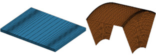
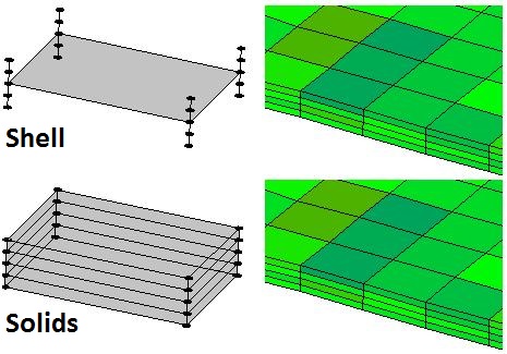 Shell element type with 5 integration points in thickness direction (top), Solid element type with 4 solids in thickness direction (bottom). On the right the result each. Shell element type with 5 integration points in thickness direction (top), Solid element type with 4 solids in thickness direction (bottom). On the right the result each.
|
|
Shell elements or solid elements?
As defined, roll forming is a pure bending method. On the shop floor, however, often massive forming occurs additionally, sometimes desirably, often undesirably. This hardly cannot be avoided, if a hem should be folded at the sheet edge with a few roll stands only. Other applications are: Desired sheet thickness modifications like e.g. forming a notch into the sheet or forming outer radii that are smaller than the sheet thickness. Deep drawing effects often occur undesirably, e.g. if two or more bending zones on one profile side are formed at the same time and the sheet edges are prevented to "flow" into the roll stand.
In order to meet these varying demands, the FEA system LS-DYNA allows selecting between shell and solid elements. Shell elements are well suited for pure bending; the calculation is quick and effective. However, limits exist if massive forming occurs. In this case solid elements are more advantageous, the calculation, however, needs more time.
The designer can select between shell and solid elements dependent on his application. The software creates the simulation model for the FEA system LS-DYNA automatically. In case of solid model, selection among 2, 4, 6, or more elements in sheet thickness direction is possible.
|
|
|
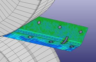
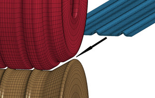
Holes and Cut-Outs:
If prepunched sheet should be roll formed, the holes/cut-outs simply can be defined in a 2D CAD drawing with any shape and position. The drawing is saved from CAD in DXF format. PROFIL extracts the holes/cut-outs from this file and copies them to the files with the simulation model.
|
|
|
Holes and Cut-Outs:
After running the FEA solver the simulation result shows if the shape and position of the holes/cut-outs is as desired in the final profile after leaving the roll forming machine.
|
|
|
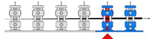
Restart After Optimizing the Roll Tools:
If the simulation result shows that rolls have to be modified, it is not necessary to repeat the whole simulation starting at the first stand. Instead, the simulation can be restarted at the certain stand whose rolls were modified. This saves computation time.
|
|
|
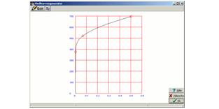
Curve Generator:
Often the exact stress-strain-curve of the used material is not available and cannot be obtained shortly. Nevertheless the designer wants to proceed a FEA simulation with approximate values. The curve generator is a handy tool for creating a stress-strain curve quickly by defining three characteristic curve points. The three points are: Yield point, tensile breaking stress point, and a medium point that controls the bulge of the curve. The curve has a tangential connection to the Hookean line (defined by the Young's modulus) and is continuous rising with rising strain (true strain for FEA, not nominal strain from the tensile test).
|
|
|
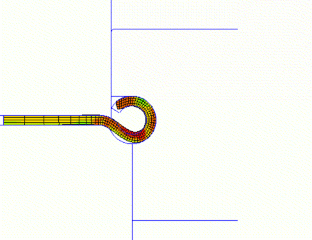
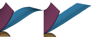
Plan vs. actual analysis:
After cutting and rotating to the 2D view the planned contour (from the flower pattern) can be compared with the actual contour (from the FEA simulation). The example shows how a faulty roll tool set forms a profile that has not the desired circular cross section at the band edge. The designer can see clearly that the side roll with vertical axis raises the curved profil bottom. The simulation gives valuable information which rolls of which stand have to be redesigned.
|
|
|
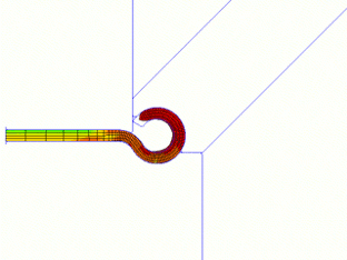
Optimizing the roll tools:
After redesigning the rolls and restart the simulation by using the time-saving restart function the profile has the desired circular cross section at the band edge. Side rolls with increasing inclination angle prevent the raising effect of the curved profile bottom. Furthermore the modified bending sequence improves the profile form. Now the rolls can be manufactured without producing scrap.
|
|
|
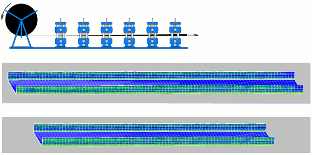
Masking out the Profile:
The simulation is proceeded by using a strip with a user-defined finite length (in reality, the strip nearly has unlimited length). Because the behavior of a finite and an unlimited strip is different, the leading and the rear edge can get unrealistic deformations. In order to mask this affect out during evaluation, a selectable count of rows can be cut off at the leading and the rear edge.
|
|
|
Threading the profile lead end into the roller stand:
If the roll forming tools should be verified by using the FEA (Finite Element Analysis) simulation, the quite short sheet section must be threaded correctly into the roller stands. In PROFIL, the user can select between several options to enable correct threading: Reducing the speed while entering the roller stand. Guiding the nodes at the profile lead end forces safe threading of the profile into the next roller stands and prevents pushing against the rollers. Guiding the nodes at the profile tail end replaces the missing subsequent strip behind it and prevents up and down oscillation. Alternatively, the sheet lead edges and be chamfered in width and in thickness direction. This improves threading. If precut blanks should be roll formed, guiding and chamfering can be switched off in order to simulate also this process correctly.
|
|
|
Start with preformed profile For saving time or other special needing, starting the simulation with a preformed profile instead of the flat sheet may be necessary. The user simply selects the pass of the flower pattern for the initial cross-section.
|
|
|
Avoiding waves at the tail end Waves can occur in case guiding is not selected while simulating thin sheet. In reality, this is normal when the coil end is reached. It however has interfering influence on the simulation result. A switch is provided to prevent oscillation.
|
|
|
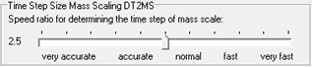
Time Step Size Mass Scaling The best time step size is dependent on the used material and the smallest element size and has great influence on robustness and precision of the simulation. Determining needs experience. In order to relieve the user from unnecessary decision, the best time step size is calculated by PROFIL. By using the slider the recommended value can be fine-tuned from very accurate until very fast.
|