| Calculating the developed length | <-- 9 10 11 12 13 --> |
|
The developed length in roll form design
The developed length of each arc segment and with it the strip width normally is calculated dependent on sheet thickness, bend radius and angle. In reality, however, there are more dependencies. Also the material, the bending method and the bend angle sequence have influence. Anyway, this was the result of most recent research at the PtU of the Technical University of Darmstadt (Germany) and this insight meets the experience of the roll form designers. This influence cannot be handled by a universally valid calculation method, but has to be defined individually and empirically. In PROFIL, a separate calculation method can be applied to each arc segment. The user can select between a standard method, such as Oehler, DIN, centerline, or define user methods that can be equipped with empirical corrections. The latter are important in case larger angle increase is necessary because of limited count of stands and subsequently occurring deep drawing effects. The new dialog window gives an overview of the existing calculation methods, enables defining user methods, and applying the methods to the profile's arc elements. In this window, the position of the neutral line is shown as a graph dependent on ri/s (ratio inner radius/sheet thickness). | |
|
Oehler method:
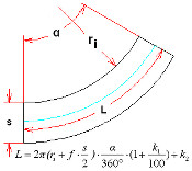
This is the most precise one of all known methods, because it calculates the developed length dependent on the sheet thickness, the bending radius and the angle. DIN 6935 method:
Centerline:
User defined methods:
|