- Rel. 6.3 Date 01-Dec-2023:
- New features:
General:
 New material model: The material model of the PROFIL FEA extension is available now in the PROFIL basic version. These calculation methods have been modified and are based on data from the new material model: Stress of band edge, PSA, spring back, stress on the outside of the bending zone. New material model: The material model of the PROFIL FEA extension is available now in the PROFIL basic version. These calculation methods have been modified and are based on data from the new material model: Stress of band edge, PSA, spring back, stress on the outside of the bending zone.
 New material database: PROFIL contains a new material database with properties and stress-strain curves of leading material suppliers. These data come from tensile tests from the suppliers. Thus the user gets more precise results from the FEA simulation. New material database: PROFIL contains a new material database with properties and stress-strain curves of leading material suppliers. These data come from tensile tests from the suppliers. Thus the user gets more precise results from the FEA simulation.
- Scaling on high resolution monitors: If the user sets a WINDOWS scaling >100% on a high resolution monitor in order to have the font better legible, the content of the PROFIL windows sometimes have been incomplete in the past. The problem now is solved; any scaling and any WINDOWS screen format can be set. Furthermore the screen font has been set to Tahoma that improves the legibility of small fonts.
- FEA Finite element analysis:
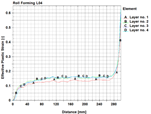 FEA evaluation: After running the solver the strain at the band edges is shown. FEA evaluation: After running the solver the strain at the band edges is shown.
- The call of the material window has been moved to the button bar of the main window in order to make is available in the PROFIL basic version.
- Horizontal guiding the reference point of a symmetric profile also is possible now in case the profile starts with an arc segment at the reference point.
- Roll design:
- Rolls, Move and Rolls, Extension with overlap: Question Move existing rolls? If answered no, rolls can be stacked in special cases e.g. if a roll should rotate on a shoulder of an adjoining roll.
- Calculate:
- The automatic trapezoidal profile forming also is possible now if the profile list contains arc types A2..A4 or a radius 0.
- File output:
- A dot in the path name also is possible now.
- Rel. 6.2 Date 01-Dec-2022:
- New features:
General:
 Spanish Version: Novedades para todos los diseñadores de perfilado hispanoparlantes: La nueva versión 6.2 64bit del software de diseño de perfilado UBECO PROFIL está ya disponible en español. Tanto la interfaz de usuario con todas las funciones de menú como los cuadros de diálogo están en español. También el fichero de ayuda de PROFIL y el Manual de Usuario de PROFIL están traducidos al español. Spanish Version: Novedades para todos los diseñadores de perfilado hispanoparlantes: La nueva versión 6.2 64bit del software de diseño de perfilado UBECO PROFIL está ya disponible en español. Tanto la interfaz de usuario con todas las funciones de menú como los cuadros de diálogo están en español. También el fichero de ayuda de PROFIL y el Manual de Usuario de PROFIL están traducidos al español.
- FEA Finite element analysis:
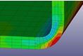 Automatic Refining: Since the profile is more deformed in the bend zones and at the band edges, it makes sense to double the count of elements in these critical zones. Automatic Refining: Since the profile is more deformed in the bend zones and at the band edges, it makes sense to double the count of elements in these critical zones.
- FEA output window more clearly by tree view explorer.
- Improved output progress protocol.
- In case of a long sheet the pass of the flower pattern is shown in all stands whose rolls have contact.
- Meshing preview with explorer and button bar; the sheet length for the preview can be set separately from the origin length.
- Bugfix: The simulation in imperial units is possible now.
- Profile design:
- Import DXF and import ActiveX: Extension to closed polylines and extension to AcDb2dPolyline.
- Bugfix: Wrong strip width after changing PS to P. All entries behind P are unconsidered.
- CAD interface:
- SolidEdge: Text height for roll and part number is exported, too.
- User interface:
- Path and file selection dialogs are changed to Vista layout.
- Bugfix: In case of imperial units the mass texts are not selectable by mouse click.
- Rel. 6.1 Date 01-Dec-2021:
- New features:
General:
 Profile, Element, Fillet: Any two line or arc elements are selected that should be rounded out with each other. Elements between the selected ones are removed, especially correction elements that arose by non-tangential connections in a faulty CAD drawing. Profile, Element, Fillet: Any two line or arc elements are selected that should be rounded out with each other. Elements between the selected ones are removed, especially correction elements that arose by non-tangential connections in a faulty CAD drawing.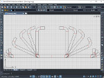
- ActiveX interface to ZWCAD: A low-cost CAD system with perpetual license that is popular in Asia. It is fully DWG compatible and has functions and commands like AutoCAD. The comfortable interface enables creating profile and roll drawings in the just opened CAD document and imports user drawn profile and roll contours from CAD.
- Sometimes, if the roll and part numbers are
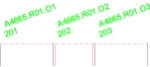 long and the rolls are small, the numbers obscure each other. Now long numbers are rotated automatically in order to prevent obscuring. The rotation angle can be preset. long and the rolls are small, the numbers obscure each other. Now long numbers are rotated automatically in order to prevent obscuring. The rotation angle can be preset.
- FEA Finite element analysis:
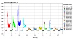 After finishing the FEA simulation of the profile project a new Python scipt shows important FEA results as a graphic automatically, e.g. the forces of the top shafts of each machine stand. The forces are important for configuring the shaft diameter, bearings, cardan shafts, gear box, and the drive power. The script easily can be adapted to individual user's needs. After finishing the FEA simulation of the profile project a new Python scipt shows important FEA results as a graphic automatically, e.g. the forces of the top shafts of each machine stand. The forces are important for configuring the shaft diameter, bearings, cardan shafts, gear box, and the drive power. The script easily can be adapted to individual user's needs.
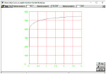 Stress-strain curve as analytic function: If the designer quickly wants to validate his project by FEA and the exact material data are not available, it makes sense to use an approximation. A new feature is to use an analytic function in the integrated curve generator. Stress-strain curve as analytic function: If the designer quickly wants to validate his project by FEA and the exact material data are not available, it makes sense to use an approximation. A new feature is to use an analytic function in the integrated curve generator.
- Stress-strain curve generator: Input fields can be modified by PgUp/Dn keys.
- Desired final pass L01 is shown in the sheet center after calculating spring back.
- Bugfixes profile design:
- Leaving the input field Strip Width is not possible.
- Missing input fields in all toolboxes (Korean version only).
- Missing update of the stress of band edge window after toggling loaded-discharged (F9).
- The stress of band edge window has to be reopened after Undo/Redo.
- Bugfixes roll design:
- Settings, Rolls: Number key sequence can be preset for variable $SA.
- Program loop if a superfluous corner point has a radius.
- Plausibility check, inaccuracy in case of large radii.
- Overlap between arcs in case of a very small contour kink.
- Number key is not considered if it differs from the previous.
- Bugfixes machine:
- Missing user request if a machine stand is removed.
- Bugfixes CAD interface:
- STEP output and others: Checking improper characters and double layer names.
- Output via ActiveX to BricsCAD, wrong text rotation angle.
- Bugfixes parts list:
- Run time error if no working sheet is opened in Excel.
- Bugfixes user interface:
- Print button, function changed to print preview.
- Rel. 6.0 Date 01-Dec-2020:
- New features:
General:
 64bit version for WINDOWS 7,8,10 enables efficient handling especially for larger projects during output. 64bit version for WINDOWS 7,8,10 enables efficient handling especially for larger projects during output.
- Roll Tool Window, Print Preview, Create Parts List, Create NC: Real diameter instead of intersection diameter of the tangents.
- Profile List: Leading zeros are displayed after entering ## in the field Pass.
- Export and all other Save functions: User request if file already exists.
- FEA Finite element analysis:
- New menu item Advanced for expert settings.
- Contacts are active only, if the sheet is near or between the rolls. This speeds up the simulation time.
- Start Position in front of the stand: Calculation dependent on the real roll radius instead of the radius at the intersection point of the tangents.
- Guideways are saved in the project file. If Restart is selected, the saved guideways are taken instead of calculating them newly dependent on the roll diameters. Thus restart is possible after modifying roll diameters.
- Improved Automatic Roll Meshing.
- New button FEA Output in the Button Key Bar.
 Roll Stock Management / Profile Catalogue: Roll Stock Management / Profile Catalogue:
- New database format SQL 64bit.
- Database converter for the transfer of old roll and project data to the new SQL database.
- Bugfixes general:
- Roll Numbering for more than 10 rolls works correctly now.
- Stress of Band Edge/PSA: No error anymore for empty profile lists.
- Print Preview: Correct form feed for NC output now.
- Roll Stock Management: No negative roll width anymore if rolls are defined from the right to the left.
- Double pass names check works correctly now.
- Short Keys are saved to the ini file correctly.
- 3D-Model -> CAD now also appears in the Short Keys selection box.
- ACAD ActiveX Import: No abort anymore if the CAD drawing contains more than one polyline.
- Bugfixes FEA Output:
- No sporadic DEATH < ENDTIM anymore.
- The profile does not stick to the top roll anymore.
- In case of guiding the birth contact start is not too late anymore, now it always starts at the largest radius.
- Profile Meshing now works correctly in case of succeeding arcs with the same length,
- No double curve point anymore in the velocity curve for a small distance between stands.
- No run-time error anymore during FEA output, if a stand contains no rolls.
- No wrong z meshing anymore after opening old projects,
- In the Curve Generator min. allowed fracture strain is now 0.01.
- In a symmetric project, the rolls now are exported to FEA correctly if they are defined from the right to the left.
|
|
|